

Grinding Applications
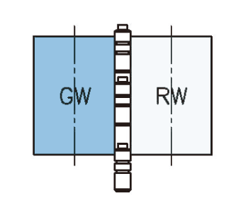
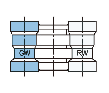
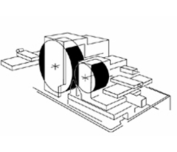
Thrufeed grinding
Thrufeed grinding
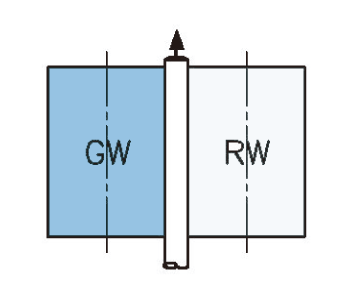
Infeed grinding
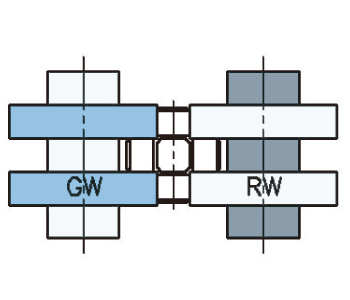
Infeed grinding
Infeed grinding
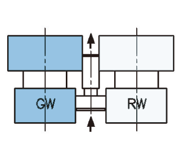
Infeed grinding
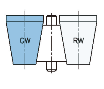
Infeed grinding
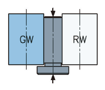
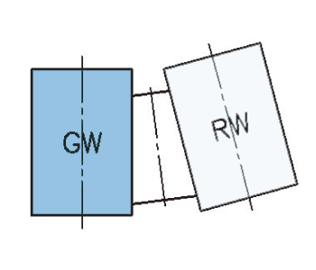
Infeed grinding
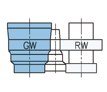
Infeed grinding
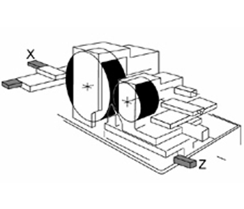
Control Axis Diagram
1 Axis
Z Axis: Upper or lower slide movement
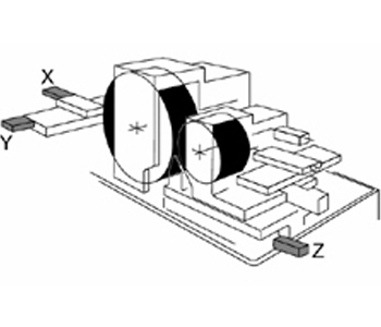
2 Axes
X Axis: Grinding wheel dressing
Z Axis: Lower slide movement
3 Axes
X, Y Axis: Grinding wheel dressing with interpolation
Z: Lower slide movement
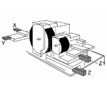
4 Axes
X, Y Axis: Grinding wheel dressing (Profile dressing)
Z Axis: Lower slide movement
Z1 Axis: Upper slide movement
5 Axes
X1, Y1 Axis: Regulating wheel with interpolation
X Axis: Grinding wheel dressing
Z Axis: Lower slide movement
Z1 Axis: Upper slide movement
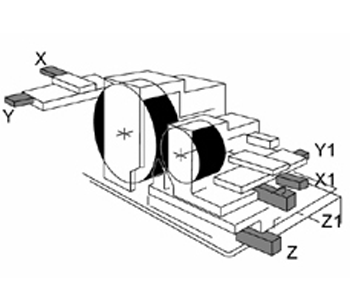
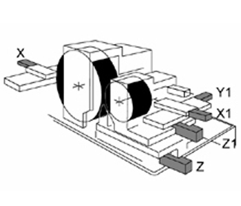
6 Axes
X, Y Axis: Grinding wheel dressing with interpolation
X1, Y1 Axis: Regulating wheel dressing with interpolation
Z Axis: Lower slide movement
Z1 Axis: Upper slide movement
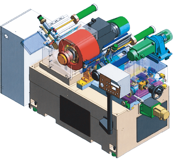
Machine Design Feature
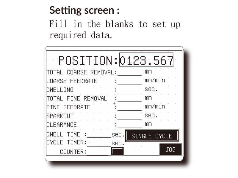
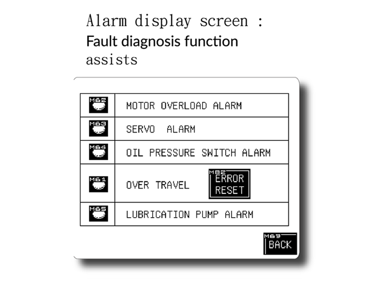
LCD Touch Screen Control Technology
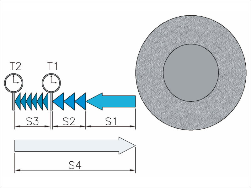
Auto-infeed Grinding Cycle
Cycle sequence:
- S1-Rapid approach
- S2-Coarse grinding
- T1-Dwell time
- S3-Fine grinding
- T2-Sparkout dwell time
- S4-Rapid retract
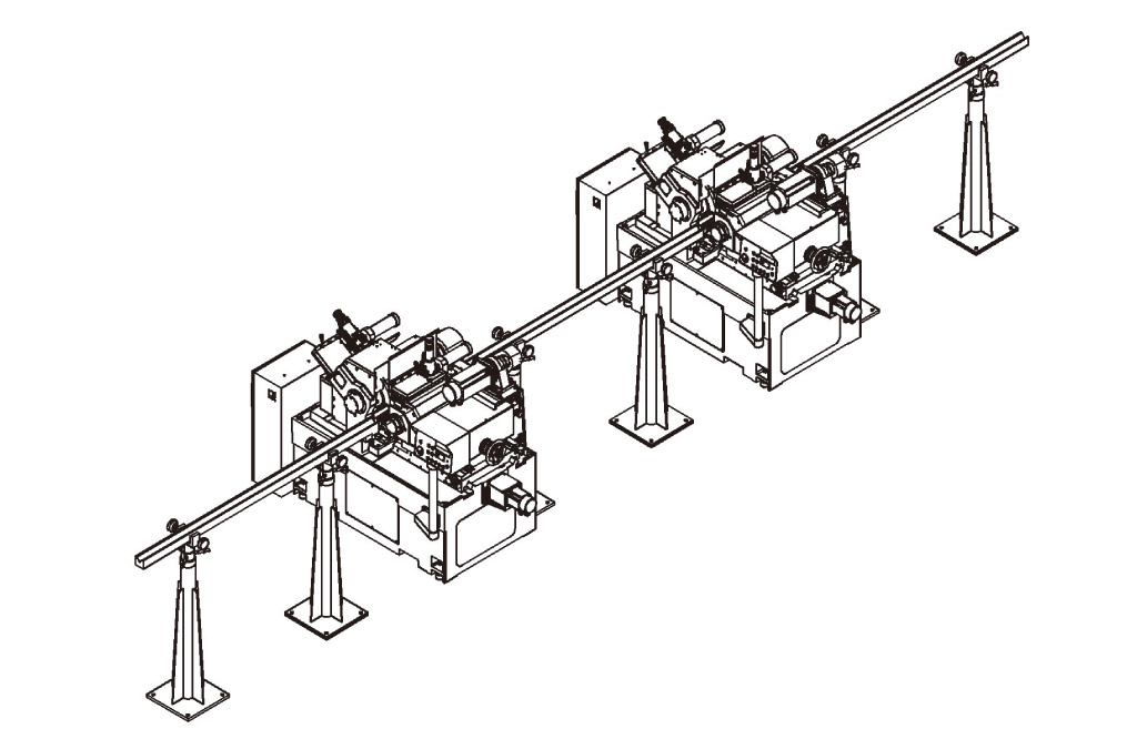
Automation Solution
Multiple machines can be linked to do rough, medium and fine grinding in one production line to save time for repetitive loading and unloading procedure.
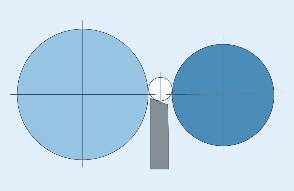
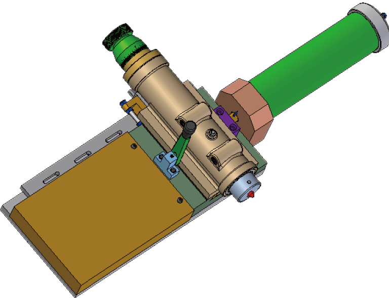
Blade Selection
Due to different working diameters, the guide plate and regulating wheel must be parallel as this influences the grinding accuracy significantly.
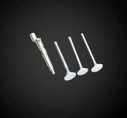
Part name:Step shaft
Infeed grinding + auto-loading/unloading
Material:SCM415
Removed stock:Max. ∅0.2mm
Cycle time:25sec(loading/unloading included)
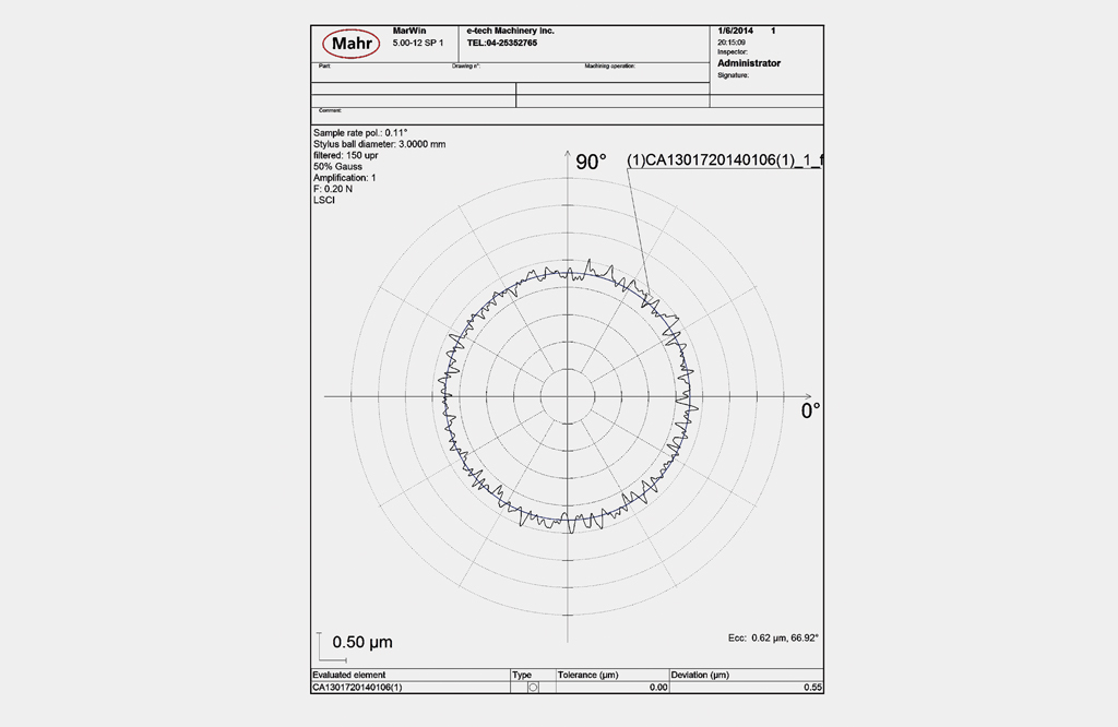
Roundness:1.5μm
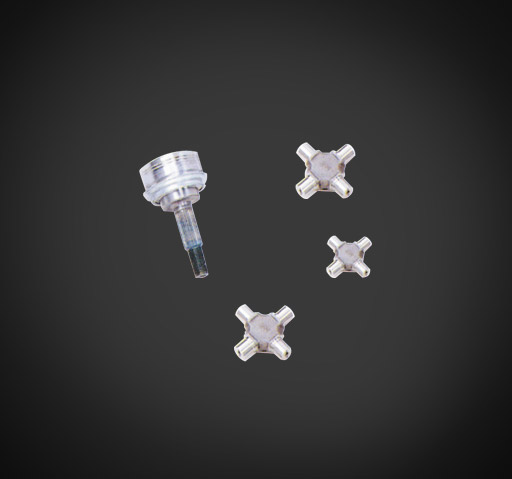
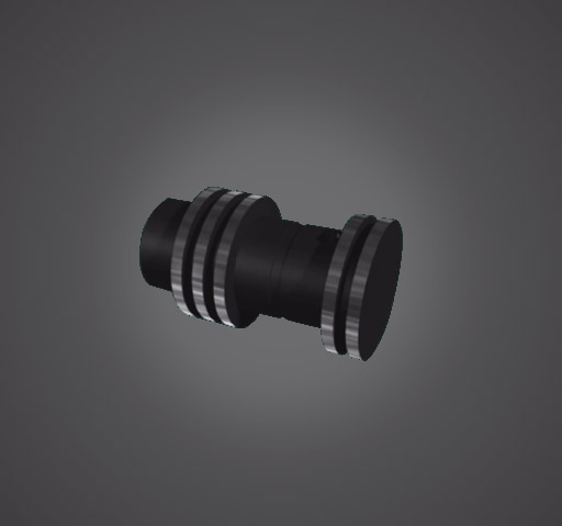
Part name:Ball Piston
Infeed grinding + auto-loading/unloading
Material:SCM415
Removed stock:Max. ∅0.3mm
Cycle time:26sec(loading/unloading included)
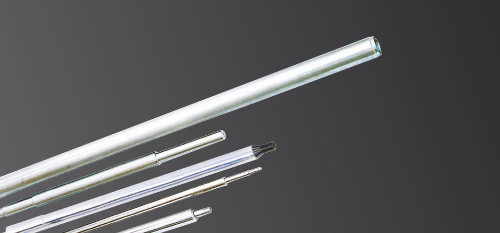
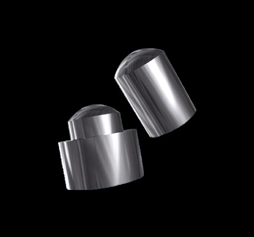
Part name:Piston pin
Thrufeed grinding
Material:SCr21H
Removed stock:Max. ∅0.13mm
Feedrate:3m/min
Roundness:1.2μm
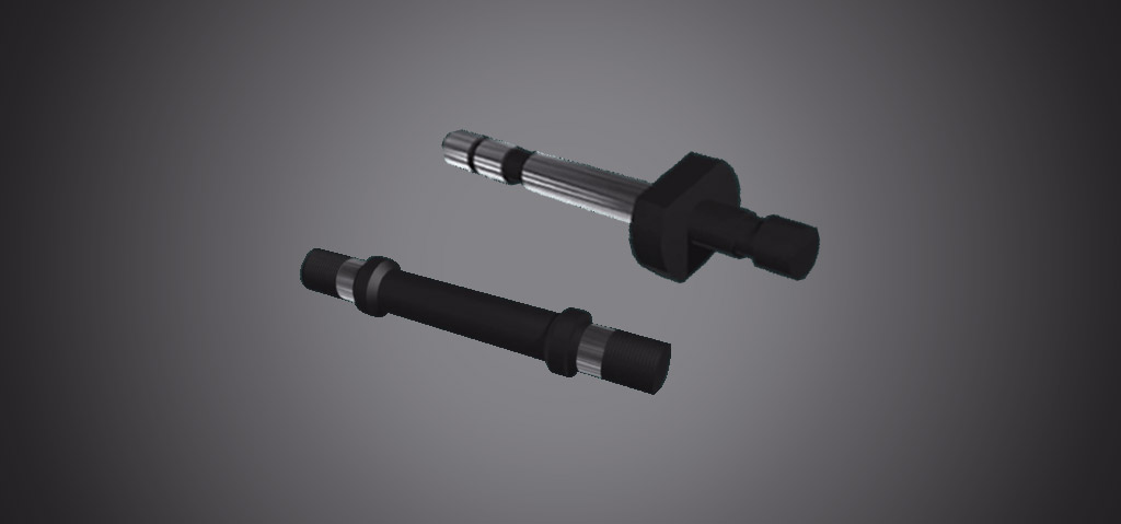
Grinding Sample
Specification
| Compare ECG-NC1206 |
Compare ECG-NC1808 |
Compare ECG-NC1810 |
Compare ECG-NC1812 |
Compare ECG-NC2008 |
Compare ECG-NC2010 |
Compare ECG-NC2012 |
Compare ECG-NC2408 |
Compare ECG-NC2410 |
Compare ECG-NC2412 |
||||
|---|---|---|---|---|---|---|---|---|---|---|---|---|---|
| Grinding Capacity | Work diameter (w/standard workrest) | mm | Ø1-30 | Ø1-60 | Ø1-60 | Ø1-60 | Ø1-60 | Ø1-60 | Ø1-60 | Ø1-80 | Ø1-80 | Ø1-80 | |
| Work diameter (w/special workrest) | mm | Ø30-50 | Ø60-100 | Ø60-100 | Ø60-100 | Ø60-120 | Ø60-120 | Ø60-120 | Ø80-150 | Ø80-150 | Ø80-150 | ||
| Auto infeed min. increment | mm | 0.0001 | 0.0001 | 0.0001 | 0.0001 | 0.0001 | 0.0001 | 0.0001 | 0.0001 | 0.0001 | 0.0001 | ||
| Grinding Wheel | Wheel size (OD x Width x ID) 08type | mm | φ305x150xφ120 | φ455x205xφ228.6 | φ455x205xφ228.6 | φ455x205xφ228.6 | φ510x205xφ304.8 | φ510x205xφ304.8 | φ510x205xφ304.8 | φ610x205xφ304.8 | φ610x205xφ304.8 | φ610x205xφ304.8 | |
| Wheel size (OD x Width x ID) 10type | mm | - | φ455x255xφ228.6 | φ455x255xφ228.6 | φ455x255xφ228.6 | φ510x255xφ304.8 | φ510x255xφ304.8 | φ510x255xφ304.8 | φ610x255xφ304.8 | φ610x255xφ304.8 | φ610x255xφ304.8 | ||
| Wheel size (OD x Width x ID) 12type | mm | - | φ455x305xφ228.6 | φ455x305xφ228.6 | φ455x305xφ228.6 | φ510x305xφ304.8 | φ510x305xφ304.8 | φ510x305xφ304.8 | φ610x305xφ304.8 | φ610x305xφ304.8 | φ610x305xφ304.8 | ||
| Motor rated power / max. torque | kw/Nm | 5.5/36(Opt. 7.5/49) | 11/71(Opt. 15/97) | 11/71(Opt. 15/97) | 11/71(Opt. 15/97) | 15/97(Opt. 18.75/120) | 15/97(Opt. 18.75/120) | 15/97(Opt. 18.75/120) | 15/97(Opt. 22.5/143) | 15/97(Opt. 22.5/143) | 15/97(Opt. 22.5/143) | ||
| Spindle speed | rpm | 2080 | 1400 | 1400 | 1400 | 1250 | 1250 | 1250 | 1050 | 1050 | 1050 | ||
| Dressing increment per gra./rev. | mm | 0.01 / 1.5 | 0.01 / 2 | 0.01 / 2 | 0.01 / 2 | 0.01 / 2 | 0.01 / 2 | 0.01 / 2 | 0.01 / 2 | 0.01 / 2 | 0.01 / 2 | ||
| Regulating Wheel | Wheel size (OD x Width x ID) 08 type | mm | φ205 x 150 x φ90 | φ255x205xφ111.2 | φ255x205xφ111.2 | φ255x205xφ111.2 | φ305x205xφ127 | φ305x205xφ127 | φ305x205xφ127 | φ355x205xφ152.4 | φ355x205xφ152.4 | φ355x205xφ152.4 | |
| Wheel size (OD x Width x ID) 10 type | mm | - | φ255x255xφ111.2 | φ255x255xφ111.2 | φ255x255xφ111.2 | φ305x255xφ127 | φ510x255xφ304.8 | φ305x255xφ127 | φ355x255xφ152.4 | φ355x255xφ152.4 | φ355x255xφ152.4 | ||
| Wheel size (OD x Width x ID) 12 type | mm | - | φ255x305xφ111.2 | φ255x305xφ111.2 | φ255x305xφ111.2 | φ305x305xφ127 | φ510x305xφ304.8 | φ305x305xφ127 | φ355x305xφ152.4 | φ355x305xφ152.4 | φ355x305xφ152.4 | ||
| Spindle speed (infinite variable) | rpm | 15-310 | 15-310 | 15-310 | 15-310 | 15-310 | 15-310 | 15-310 | 15-310 | 15-310 | 15-310 | ||
| Upper slide infeed handwheel per gra./rev. | mm | 0.02 / 4 | 0.05 / 3.5 | 0.05 / 3.5 | 0.05 / 3.5 | 0.05 / 3.5 | 0.05 / 3.5 | 0.05 / 3.5 | 0.05 / 3.5 | 0.05 / 3.5 | 0.05 / 3.5 | ||
| Upper slide micro infeed handwheel per gra./rev. | mm | N/A | 0.001 / 0.02 | 0.001 / 0.02 | 0.001 / 0.02 | 0.001 / 0.02 | 0.001 / 0.02 | 0.001 / 0.02 | 0.001 / 0.02 | 0.001 / 0.02 | 0.001 / 0.02 | ||
| Swivelling angle (L/R) | deg | ±5° | ±5° | ±5° | ±5° | ±5° | ±5° | ±5° | ±5° | ±5° | ±5° | ||
| Inclining angle (F/R) | deg | +5° ~ -3° | +5° ~ -3° | +5° ~ -3° | +5° ~ -3° | +5° ~ -3° | +5° ~ -3° | +5° ~ -3° | +5° ~ -3° | +5° ~ -3° | +5° ~ -3° | ||
| Dressing increment(X1,Y1) per gra./rev. | mm | 0.01 / 1.5 | 0.01 / 2 | 0.01 / 2 | 0.01 / 2 | 0.01 / 2 | 0.01 / 2 | 0.01 / 2 | 0.01 / 2 | 0.01 / 2 | 0.01 / 2 | ||
| Regulating wheel motor | kw | 2 | 3 | 3 | 3 | 3 | 3 | 3 | 5 | 5 | 5 | ||
| Infeed servo motor (NC) | kw | 1 | 1 | 1 | 1 | 1 | 1 | 1 | 2.5 | 2.5 | 2.5 | ||
| Motors | Hydraulic motor | kw | 0.75 | 0.75 | 0.75 | 0.75 | 0.75 | 0.75 | 0.75 | 0.75 | 0.75 | 0.75 | |
| Machine | Net weight | kg | 1800 | 3300 | 3300 | 3300 | 3400 | 3400 | 3400 | 6100 | 6100 | 6100 | |
| Gross weight | kg | 2200 | 3600 | 3600 | 3600 | 3700 | 3700 | 3700 | 6600 | 6600 | 6600 | ||
| Packing size (L x W x H) | mm | 2260x1950x1820 | 2700x2240x1850 | 2700x2240x1850 | 2700x2240x1850 | 2700x2240x1850 | 2700x2240x1850 | 2700x2240x1850 | 3580x2240x2070 | 3580x2240x2070 | 3580x2240x2070 | ||
Standard accessories
| Tools and tool box |
| Standard coolant tank |
| Wheel extractor |
| Diamond dresser |
| Levelling bolts and blocks |
| Grinding wheel with flange |
| Regulating wheel with flange |
| Spindle lubrication system w/ cooling fan |
| Regulating wheel with flange |
| Manual lubricator for guide ways (S model) |
| Operation manual and part lists |
| Thrufeed workrest |
| Infeed workrest |
| Control panel (S model) |
| PLC controller + touch screen + control panel (NC model) |
| FANUC 0i-TF CNC controller (CNC model) |
Optional accessories
| Vibration feeder auto. loading system |
| Auto. unloading system for thrufeed grinding |
| Forming attachment (forming plates) |
| Coolant system with magnetic separator |
| Thrufeed blade (various sizes) |
| Infeed blade (various sizes) |
| Hydraulic forming attachment |
| Coolant system with paper filter |
| Coolant system with magnetic separator & paper filter |
| Infeed grinding workpiece eject attachment ( hydraulic / pneumatic ) |
| Auto. loading system for thrufeed grinding (Φ5∼25mm, L 50∼600mm) |
| Hopper type auto. loading system for thrufeed grinding (Φ2∼8mm, L 50∼180mm) |
| Input rail & output rail |
| Balancing stand/ arbor |
| Spare regulating wheel flange |
| Spare grinding wheel flange |
| CE standard electrical cabinet |
| Special workrest (for large dia. Workpiece) |
| Minor diameter workrest (dia. 0.7~8mm) |
- NC model: optional auto. grinding wheel dressing device enables count dressing, time dressing, or auto dressing and compensation
- CNC model: with two axes servo control and the automatic compensation system can precisely dress forms with complicated shapes.
- Various workrest design: E-tech developed various kinds of workrest based on different diameter of workpieces, which are easy for operating adjustment.
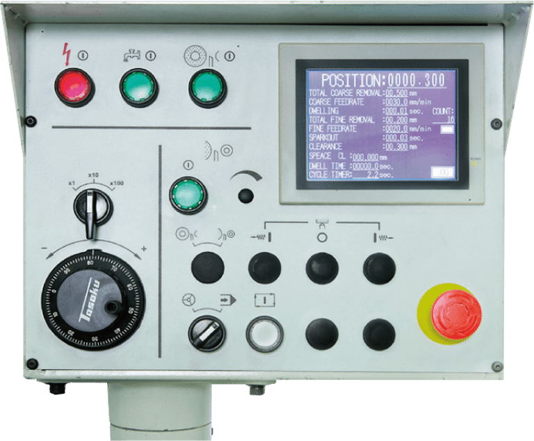
An infeed grinding cycle can be completed by simply choosing the grinding cycle mode (single or automatic), inputting grinding data and then pressing cycle start.
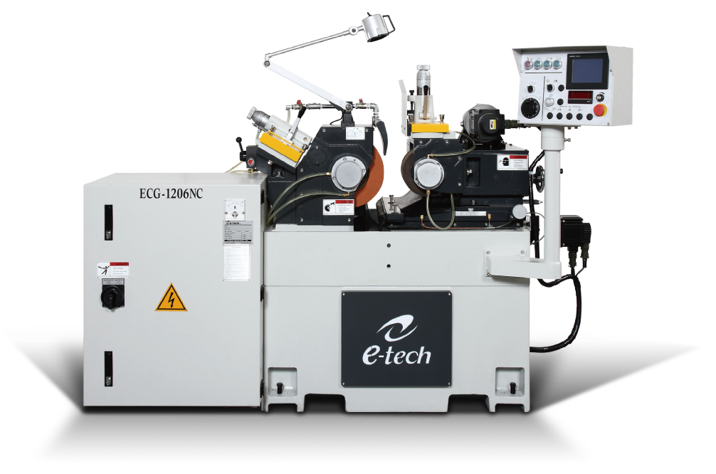
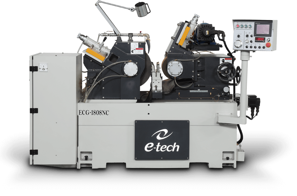
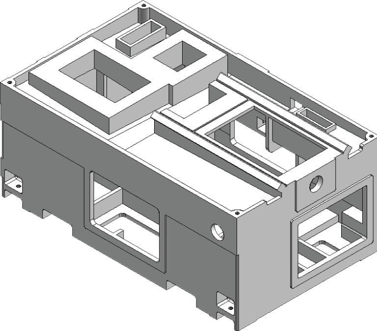
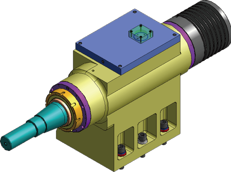
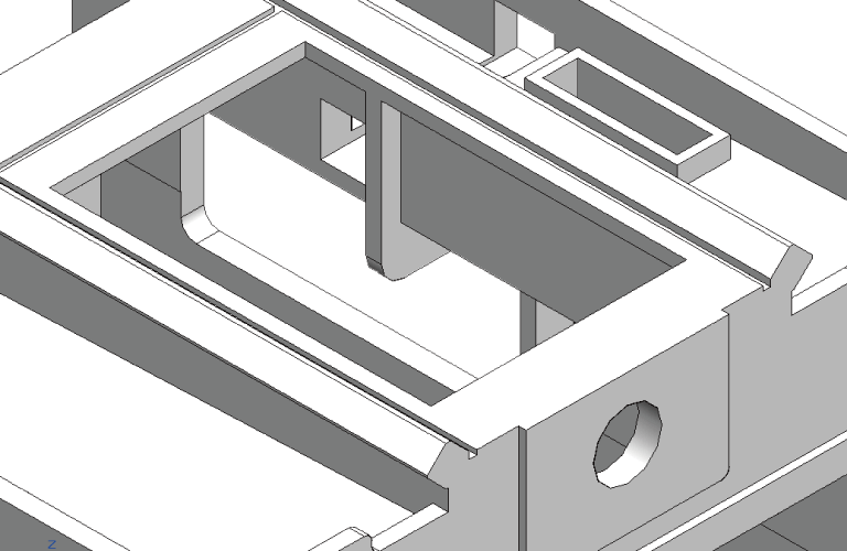
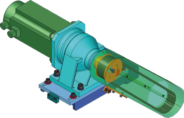
ECG series high precision centerless grinder is different from other competitors, we use spectrum analyzer to precisely analyze the machine base inner ribs and casting thickness for greater rigidity. We offer hydrodynamic alloy bearing spindle with best rotation accuracy, suitable for heavy duty jobs, and drastically increase the spindle longevity.
With all the advantage of S series, NC series further offers lower slide (Z axis) with servo motor driven design which enables the infeed position located precisely, and the infeed distance can be controlled by numerical value.
Auto. grinding wheel dressing and compensation system can be equipped as optional accessories and led to easy computer numerical control grinders for operators.